
Miscellaneous Study
Imprint Separation Study
The purpose of this experiment was to develop a method to simulate the actual imprint process and to measure the adhesive force required for separation. Parts were fabricated to connect to an Instron 5848 tensile apparatus and to replicate the SFIL film stack as illustrated in Figure 12.
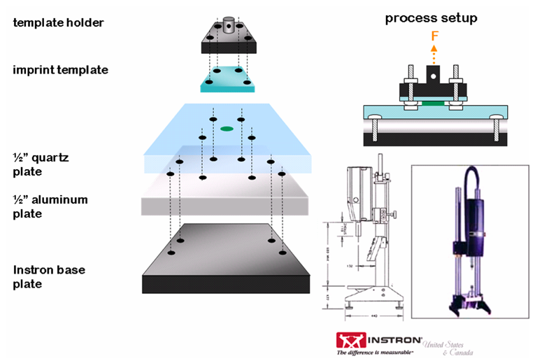
Figure 12. Retrofitted Instron tool for adhesive force measurements. A thick quartz plate is used as the imprint substrate, and the imprinted polymer is sandwiched between this quartz plate and the imprint template.
A 1/2 inch aluminum plate was fabricated to support a 1/2 inch quartz plate and to attach onto the Instron tool's base plate. Another aluminum plate was designed to hold a standard 65 mm x 65 mm SFIL template and to attach onto the Instron's load cell. All parts were bolted directly to the Instron tool to minimize any deflection generated from the pulling process. Figure 13 illustrates the standard procedure used to set up and conduct an imprint on the Instron tool.
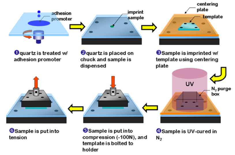
Figure 13. Imprint process using the retrofitted Instron tool.
A typical output from our experiments is illustrated in Figure 14. The sample is initially in compression (point A) as indicated by the negative load. At point C, the sample goes into tension, and the load versus extension trend follows a linear path until point D in which the imprint begins to peel away from the template. At point E, the sample completely separates from the quartz, and the load returns to zero. This trend was observed for all the trials, and the energy was compared among the samples by integrating under the curve.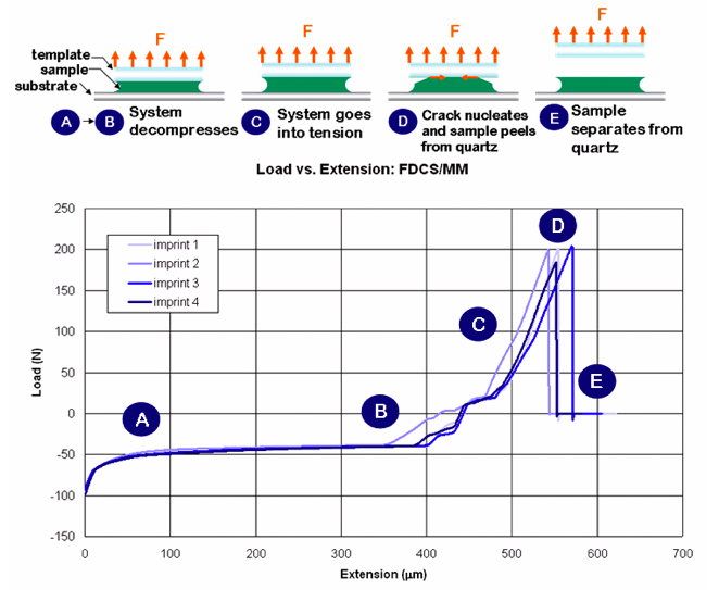
Figure 14. Load versus extension output for Instron imprint simulation experiment.
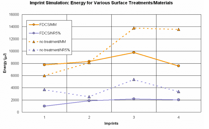
Figure 15. Separation energy for various imprint material and surface treatment combinations.
For the FSAM treated templates (FDCS), the etch barrier with surfactant (NR5%) formulation yields about 4X decrease in the separation energy compared to the MM base case. This result supports the earlier conclusion that adding surfactants to the imprint formulation does indeed lower the interfacial adhesion. The bare quartz (no treatment) cases produce an interesting result. Although surfactant migration was proven not to occur using a quartz surface, the NR5% formulation still provides a reduction in the separation energy compared to the base etch barrier (MM) case. One explanation for this result might be the surfactant stays uniformly distributed in the polymer matrix. This would lower the modulus of the imprinted film, and according to the Griffith criterion should decrease the separation force.
Contamination Study
The purpose of the contamination study was to study the durability of the FSAM layers over multiple imprints. Quartz blocks with dimensions of 1/2 inch x 1/2 inch x 1/4 inch were cut to represent the imprint template. The blocks were cleaned and treated with a standard FSAM treatment. The tested imprint materials included the standard organic etch barrier with and without 5 wt% surfactant loading. Four blocks were assigned to each group with one of the blocks serving as a control. Each of the remaining three blocks was then imprinted on a silicon wafer. Every 15 imprints, the surfaces of all the blocks were then analyzed using XPS to track the F/C and silicon atomic concentrations.
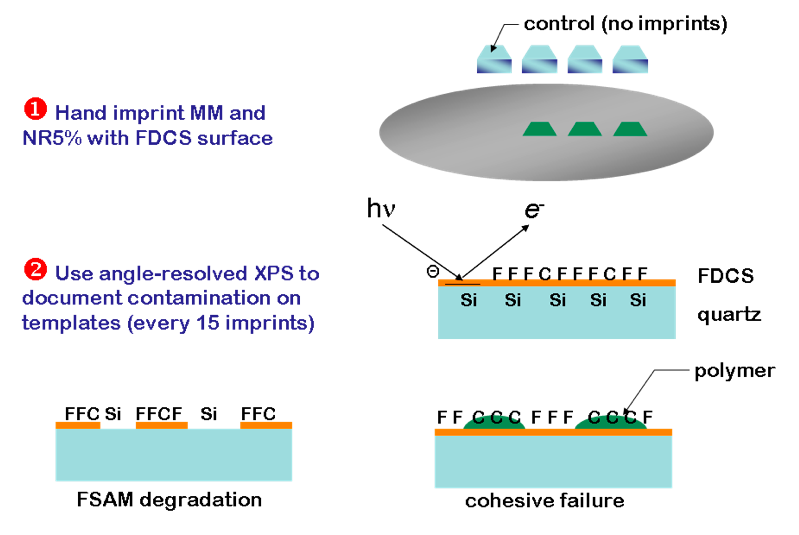
Figure 16. Contamination study procedures.

Figure 17. Contamination study of FDCS and MM.
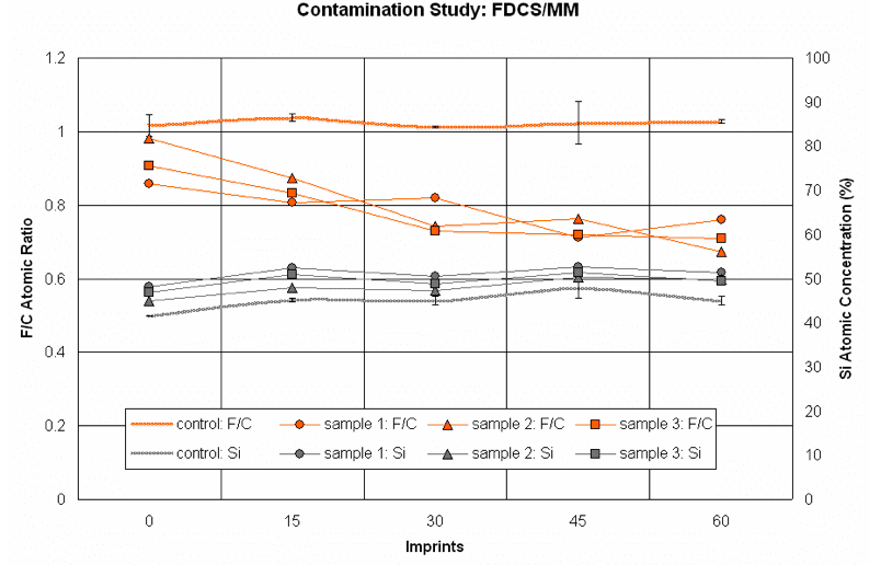
Figure 18. Contamination study of FDCS and NR5%.
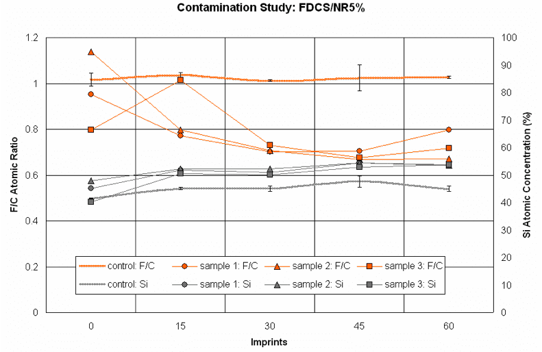
Figure 19. Contamination study of FDCS and R5%.
Figure 17 clearly shows that when using the MM material, the FDCS layer degrades over repeated imprints as the F/C trends for the samples and control diverge. This conclusion is supported by the fact that the silicon signal increases, indicating quartz (SiO2) that is devoid of any surface treatment is being detected. According to Figure 18, the NR5% case shows nearly identical results to the MM case. Thus, there does not appear to be any significant evidence that the local surfactant layer protects the FDCS from chemical or physical attack. The R5% yields slightly more encouraging results: on average, the F/C ratio is higher than the MM and NR5% cases. However, sample 3, which yields the highest F/C ratio, also shows a decrease in the silicon signal.This result might indicate that the fluorinated material is cohesively failing on the quartz surface. Unfortunately, the main conclusion from this study is imprint materials with surfactant do not prevent FSAM degradation any better than imprint materials without surfactant. Compounding the problem is the fact that the FSAM layer is responsible for inducing surfactant migration to the template-polymer interface. Therefore, more stable alternatives to FSAM might be necessary when using fluorinated surfactants.
Support and Collaborations