
Pinning
Proposed theory for pinning of air-liquid interface
The Young-Laplace equation relates the pressure difference, ΔP , between the two phases (air and liquid in this case), and the curvature of the surface with two principal radii of curvature R1 and R2 as
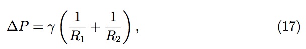
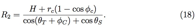
where γ is the surface tension of the liquid. For the case of trench edge with H (residual layer thickness) << L (length of a trench), the effect of lateral radius, R1 , which is essentially infinite, can be neglected; and the other radius, R2 , can be expressed in terms of contact angles, residual layer thickness and two other corner parameters: (i) angle φC and (ii) radius of curvature of the feature edge rc (see Fig. 9) as
Hence, the pressure drop across air-liquid interface at the trench edge, ΔP1 , and the driving pressure gradient for liquid spreading, ΔP2 , are ex pressed as
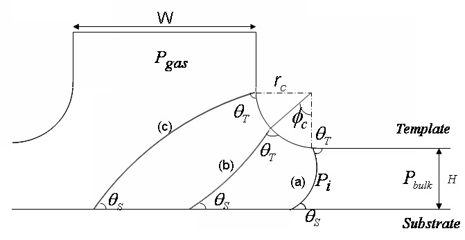
Figure 9: Schematic (not to scale) of pinning phenomenon around the trench edge. Figure illustrates air-liquid interface profiles for (a) φC = 0o , (b) 0o < φC < 90o and (c) φ= 90o
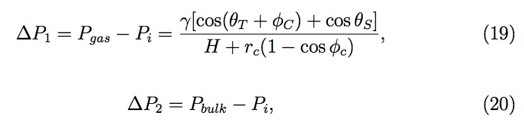
where Pbulk is the liquid pressure in the bulk, Pi is the liquid pressure at the interface as shown for interface 'a' in Fig. 9, and Pgas is the pressure of a gas, either trapped or open to the atmosphere, in the feature. Note that Pgas = Patm (atmospheric pressure) if the feature is open to atmosphere. However, for the case of entrapped gas in the feature, Pgas ≥ Patm since the diffusion stops once Pgas approaches Patm (liquid resist is assumed to be saturated with He gas in the present model, at Patm initially). Further analysis is done assuming the minimum possible value of 1atm for pressure Pgas.
Now, for a given Pbulk , a higher pressure drop ΔP1 across the interface due to capillary action increases the pressure gradient ΔP2 , which eventually results in better liquid spreading across the mesa. As the interface moves around the feature edge, the angle φC varies from 0o to 90o , decreasing ΔP1 and consequently ΔP2 . Here, we have neglected the contribution of the radius of curvature of the feature edge, assuming rc << H . The case where rc ~ O(H ) is discussed later. At a certain value of φc , the pressure drop across interface ΔP1 may decrease to an extent that Pi equals Pbulk and ΔP2 goes to zero and eventually no driving force exists for liquid to flow further into the feature. This is the point where the interface 'pins' and the feature remains unfilled (shown in Figs. 2(a) and 2(b)). Mathematically, air-liquid interface pins when pinning condition, Pbulk = Pi , holds. Fig. 10 shows ΔP2 /Patm as a function of angle φC for different values of template contact angle, θT, with a fixed substrate contact angle and residual layer thickness. The pressure gradient ΔP2 decreases as angle φC increases. For template features with vertical side wall angles, angle θ increases from θo to
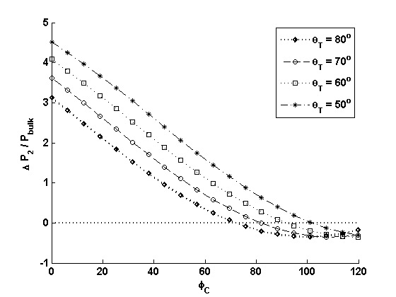
Figure 10: ΔP2/Patm as a function of angle φC for different values of template contact angle θT with fixed substrate contact angle (θS = 30o) and residual layer thickness (H = 100nm). Broken line represents the pinning condition with no pressure gradient.
90o and pinning occurs if ΔP2 goes to zero before interface reaches the angle φC = 90o. The bulk pressure can be related to the force applied on a stationary tem plate with complete spreading across the mesa with area AM (pre-exposure condition) as

Therefore, a positive imprint force would yield a Pbulk and Pi greater than Patm for pinning (Pbulk = Pi ) to occur. With Pgas = 1atm, a Pi value greater than atmospheric pressure means a net pressure increase across the air-liquid interface. In other words, the curvature of the interface changes from concave to convex, which can be mathematically stated as φC + θT + θS > 180o (see Eq. (19)). The above discussion for trench (recessed feature) also applies for line (protruding feature) on the template. However, pinning may only occur at a feature edge where the liquid undergoes an increase in thickness (in the direction of liquid flow) and thus also increasing the angle, φC .
Residual Layer Thickness
Residual layer thickness (gap 'H' between the template and the substrate) can be varied to avoid potential pinning at the feature edge. Consider the case of liquid pinning at both edges of a trench (as for an isolated trench), shown in Fig. 11. Depending on the trench width, the two lower contact lines could meet to form an upward facing concave meniscus. Thereafter, liquid fills the feature by the rapid diffusion of a gas entrapped in the features, through liquid resist. It remains unclear in Fig. 2(b) if the substrate surface has been completely wetted by the liquid resist and therefore no conclusion can be made regarding the above proposition. The geometry of the system (see Fig. 11) limits the maximum width of the feature that can be filled for a given residual layer thickness with the above phenomenon i.e. feature with larger width demands thicker residual layer for complete filling. The following relation can be derived by equating the horizontal distance covered by each interface to half of the feature width
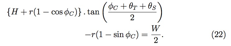
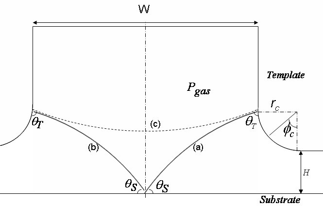
Figure 11: Schematic of pinning at both the edges of a trench. The lower contact lines of two interfaces (a) and (b) can meet to form upward facing concave meniscus (c).
Thus dispensed drops arrangement of resist during the imprint step should be such that larger features land directly over liquid drops, for complete feature filling through rapid gas diffusion and also avoiding any potential pinning.
Wettability of feature edges
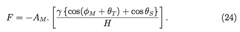
As seen in Eq. (19), it is not just the angle φC , but the summation of the two angles, θT and φC , (assuming rc << H ) that determines the pressure drop, ΔP1 , and thereby the pinning for the constant substrate contact angle, θS. Hereafter, we will refer to the summation of these two angles as "pinning angle", which represents the net effective angle of interface at the upper contact line with arbitrary horizontal surface. Therefore, for template features with vertical side wall angles, the angle θT should be minimized at the feature edges by raising the surface energy and creating a hydrophilic surface for the typical organic resist. However, the lower energy surface is preferable for better template release, and therefore the optimal surface properties are required to deal with the tradeoff between better template release and lesser pinning. Increasing the template surface energy only around the features edges could be one of the possible solution. Using Eqs. (19) and (21), pinning condition (Pbulk = Pi ) and assumption (Pgas = Patm) , one can relate pinning angle with imprint force as
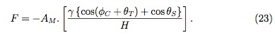
Fig. 12 demonstrates the relationship between the pinning angle (φC +θT ), and the residual layer thickness for different imprint forces. Once the curva ture of the interface changes (φC + θT + θS > 180o ), a higher residual layer thickness implies a lower pressure increase (Pi - Pgas ) across the interface, which subsequently results in pinning, if any, at a higher pinning angle for positive imprint force. Also, a high imprint force increases the pinning angle needed for Pi to become equal to Pbulk (pinning condition).
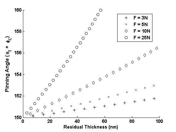
Figure 12: Plot showing pinning angles as a function of residual layer thickness for different imprint forces F = 3N, 5N, 10N and 25N (θS = 30o )
Applied force on template
The liquid spreading can be enhanced by increasing the applied force on the template, which subsequently raises Pbulk and thereby ΔP2 . The maximum force that can be applied on the template is limited by the template deformation and the extrusion of liquid resist at the mesa edges. For a stationary template with complete spreading across the mesa (pre-exposure condition), a similar relation, as given by Eq.(23), holds between the imprint force and the angle, φM , which the interface makes at the edge of the mesa (like angle φC in Fig. 9)
Now, for a fixed residual layer thickness and substrate contact angle, a maximum positive force F can be applied under the condition φM +θT = 180o . This implies that for a given φM (90o for vertical mesa edge), θT should be adjusted at the mesa edge to meet the condition. Earlier work by Bailey et al. has demonstrated a template surface treatment using a fluorinated self- assembling monolayer (FSAM) to provide a low surface energy coating, which increases the contact angle θT . (Note: the lower surface energy requirement for a mesa edge is the opposite of that required for a feature edge. A lower surface energy at a mesa edge ensures pinning to avoid any extrusion while a higher energy at a feature edge prevents pinning to facilitate better filling.) Also, the maximum possible value of φM can be made greater than 90o by fabricating a retrograde mesa edge, which allows a higher imprint force before any extrusion occurs. Fig. 13 illustrates the above mentioned two cases.
Fig. 14 depicts the process windows for the SFIL imprint step at different imprint forces. Consider the case where F = 3N. The curve AB represents the maximum trench width that can be filled for a given residual layer thickness (see Eq. (22)). The angle, φC , increases as residual layer thickness increases from point A to B, and at point B, the air-liquid interface crosses the maximum possible value of φC i.e. 90o . Beyond this point, any increase in the residual layer thickness will completely fill the trench of any width. Curve DE is dictated by the maximum residual layer thickness possible that could result an imprint force of 3N without any extrusion, assuming the maximum force condition, φM + θT = 180o , holds (see Eq. (24)). Thus, the region between curves ABC and DE represents the "no pinning and no extrusion" region for F = 3 N. The difference between residual layer thicknesses for curve BC and DE is due to the higher maximum pinning-angle (φM + θT ) at the mesa edge compare to the maximum pinning-angle (90o + θT ) at the feature edge since retrograde mesa edge is considered. This difference would be zero for the case of perfectly vertical side-wall at the mesa and the feature (trench) edges. A higher imprint force can be applied to fill a feature with a larger width for a given residual layer thickness but at the expense of an operating region of high residual layer thickness (see F = 5N in Fig. 14).
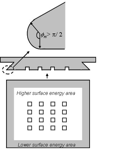
Figure 13: Schematic of the proposed template for better filling of features without any extrusion. The retrograde mesa edge (side view) and surface energy gradient (top view) in the template will ensure pinning of the air-liquid interface at the mesa edge and facilitate superior filling of template features.
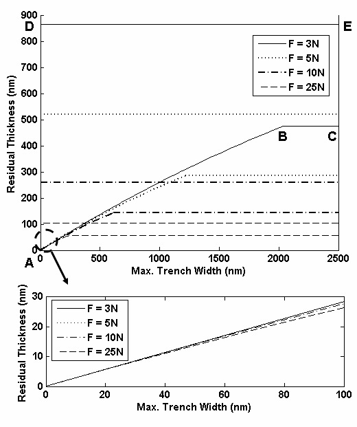
Figure 14: Imprint process windows (no pinning and no extrusion region) at different imprint forces. (θT = 70o , θS = 30o )
Radius of curvature of the feature edge
In the previous analysis, we assumed the case where the radius of curvature of the feature edge is negligible in comparison to the residual layer thickness. However, when rc ~ O(H ), it can assist feature filling under most operating circumstances of positive imprint force applied on the template (refer Eq. (19)). A larger radius of curvature at the feature edge increases the effective residual layer thickness by the amount rc (1 - cos φC ), and thus increases the radius of curvature of air-liquid interface (refer Eq. (18)). This results in a lower pressure change, |ΔP1 |, across the interface for a positive imprint force. On the other hand, the pinning requirement at the mesa edge (to prevent extrusion) demands a minimal radius of curvature at the mesa edge. Above a certain rc /H ratio, the air-liquid interface always succeeds in crossing over the threshold value of φC at which Pi is maximum (which may not necessarily be 90o in this case). A required linewidth control determines the maximum tolerable rc /H ratio. Fig. 15 exhibits the minimum rc /H ratio to avoid pinning regardless of feature size for different imprint forces.
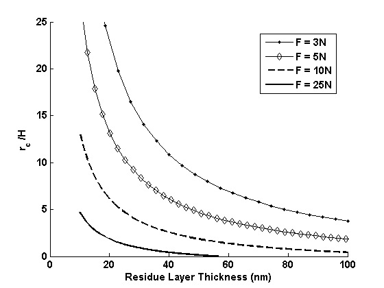
Figure 15: Plot showing minimum rc /H ratio, sufficient to prevent pinning regardless of feature size, as a function of residual layer thickness for different imprint forces. (θT = 70o , θs= 30o )
Concluding, the pinning of air-liquid interface at template features is found to be the cause for non-filling of features in the SFIL imprint step. A theory of pinning of an air-liquid interface at feature edges is developed and presented. Pinning results because of the change in pressure drop across the air-liquid interface and thus leads to no pressure gradient in liquid bulk for liquid flow. The analysis demonstrates that the larger width features require higher residual layer to fill without pinning. It is shown that pinning should be more favorable at the mesa edge compare to the feature edge for better feature filling. Furthermore, measures like larger radius of curvature at feature edge, retrograde mesa edge and surface properties modification at mesa and feature edges are found to aid better filling without pinning and any extrusion along the mesa edge. The SFIL process window is described for different imprint forces and can be chosen based on required pattern design. Thus, we believe this study could be decisive in determining the optimal operating conditions for defect-free SFIL imprint step.
Support and Collaborations