|
||||||||||
|
SFIL Overlay
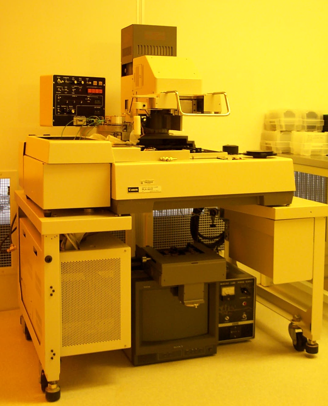
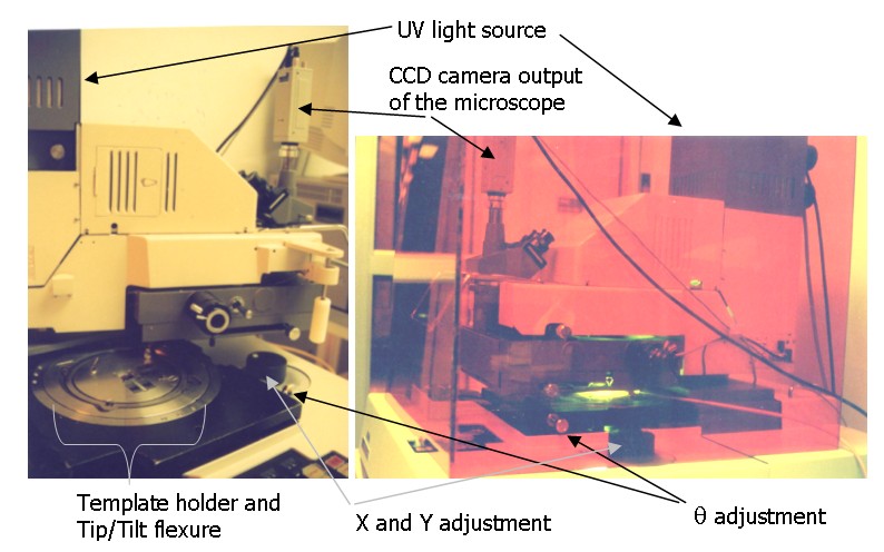
Alignment Machine The Overlay Alignment Machine (OAM) was developed to demonstrate layer-to-layer alignment with SFIL [Choi et al. 2001]. The OAM is a Canon 501 parallel light mask aligner, shown in Figure 1, that has been modified to implement a multilayer SFIL process. The original mask holder was modified to hold a low-profile 2-degree-of-freedom tip/tilt flexure with a mating SFIL template holder (see Figures 1 and 2). The bulk of the machine is below the level of the template holder; above the template holder is a microscope and exposure assembly. This assembly is used for the blanket UV exposure of the S-FIL process, and for looking through the template to align the features of the template to those on the wafer. The image of the features on the template and wafer are focused on a CCD camera, which is displayed on a monitor. The assembly is normally directly above the wafer/template stack, but can pivot to the side for removal of the template holder and the wafer. Figure 3.2 shows two views of the OAM – with the microscope and exposure assembly pivoted to the side (left) and directly over the wafer (right).
Figure 1. Canon 501 parallel light mask aligner, prior to modification.
Figure 3.3. The S-FIL tip/tilt flexure assembly (left) and template holder (right). The lower parts of the machine contain the template and wafer holding and alignment assemblies. The template holder and tip/tilt flexure assembly can be seen on the machine in the left image of Figure 2. Figure 3 shows the template holder (right) and tip/tilt flexure (left) separate from the machine. The tip/tilt flexure is mounted to the frame of the machine above (and around) the wafer, wafer-chuck, and XY adjustment assemblies. The template holder assembly sits on the tip/tilt flexure and is held in place by a vacuum pulled in the outer margin of the template holder. The template is held in the template holder by set-screw-driven pistons. The wafer chuck is below the template holder, and is attached to an air piston by a spherical bearing. The alignment of the template to the wafer is done with the combination of passive and active elements. The wafer chuck is pushed upwards toward the template to imprint, narrowing the gap in the Z-direction by the air pressure in the air piston, and dampened by the etch barrier film between the template and the wafer. Rough alpha and beta alignment is achieved by a pre-calibration step utilizing the spherical bearing below the wafer chuck and the tip/tilt flexure. The wafer chuck is brought up and the top-side of a lower extremity of the chuck comes into contact with the bottom-side of the flexure ring. Fine alpha and beta alignment is achieved passively during imprinting with the tip/tilt flexure. The tip/tilt flexure was designed for selective compliance for passive alignment in the a and b motions, with the center of rotation at the template/wafer interface, with low deflections X, Y, and Z [Choi et al. 2001]. Theta is adjusted by rotating the template via the tip/tilt flexure and template holder assembly. The range of motion for theta is about 10 degrees, and continuous with no noticeable backlash. X and Y adjustment is done with the original mask-aligner mechanisms. This adjustment has +/- 0.1” range in X and Y and 0.5 micron resolution, and has no problem moving the wafer when it is in full fluid contact with the template. Submicron alignment has been demonstrated with this machine [Choi et al. 2001]. The machine is not capable of magnification or distortion corrections. The machine was not designed to have a high throughput - the OAM is designed to only imprint on the center of 4” wafers. There is the capability for XY movement of the wafer chuck relative to the template assembly, but the range-of-motion is used for layer-to-layer alignment only. There is only one microscope objective, so X,Y, and q alignment is an iterative process. For each imprint, the exposure and microscope assembly is pivoted to the side, the template holder is removed, a new wafer is placed on the wafer chuck, the monomer solution is dispensed, the template holder is put back in place, and the exposure and microscope assembly pivoted back to center. The placement of the wafer on the wafer chuck is important – the wafer must be placed within motion range of the X,Y, and q adjustments. The monomer solution is dispensed by hand with a micropipette, a process that allows for error in dispensed volume and drop placement. This machine has been used to pattern the gate level of a MOSFET device.
| ||||||||||
|
|
||||||||||