|
||||||||||
|
SFIL Passive
Flexure Orientation Stages Imprint lithography relies on the parallel orientation of the imprint template and the substrate. Inaccurate orientation may yield a layer of cured etch barrier that is non-uniform across the imprint field, and attempts to amplify the aspect ratios of the imprinted image will serve to amplify this non-parallel effect. It was therefore necessary to develop a mechanical system whereby the template and substrate are brought into co-parallelism during etch barrier exposure. This is achieved in SFIL by way of a two step orientation scheme. The first step is an active, user-controlled, global or wafer-scale orientation, wherein the template stage holder and wafer chuck are rotated about the a and b axes to bring the two surfaces into approximate parallelism, and is shown schematically in Figure 1. Figure 1a represents an improperly aligned system. The flexure-based course orientation stages, one each placed below the wafer chuck and above the template stage, allow one translation motion (Z displacement) and two tilting motions (a and b rotation), Figure 1b. The passive, fine orientation stage affects the system during imprinting to achieve perfectly uniform surface contact between the template and substrate, Figure 1c.
Figure 1. Improperly oriented template and substrate system (a), desired orientation alignment motions (b), and properly oriented system ready for imprinting (c). The SFIL orientation scheme incorporates both an active, course orientation that is used to correct global, or wafer-scale parallelism issues, and a passive, fine orientation that minimizes local misorientation. Figure 2a shows an ideal kinematic stage composed of perfect rigid bodies and joints. The ideal kinematic stage has several practical limitations with respect to the SFIL process. The presence of sliding contacts in joints can cause wear, generating particles and leading to stiction that makes precision motion control difficult. The presence of clearances in joints can lead to reduced repeatability in the motion of the mechanism. Flexures generate motion by elastic deformation, avoiding all the problems associated with joints, and are becoming quite common in the precision engineering industry.1,2
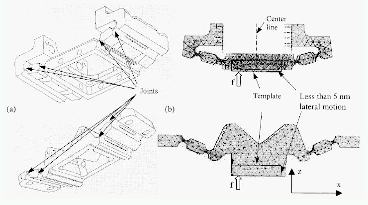
Figure 2. The passive orientation scheme. Ideal kinematic model (a), which allows the proper degrees of freedom, a and b rotation, and z translation. Single axis template stage design (b), using only flexure joints, which complies to the DOF constraints. This design has been extended to a two-axis design for SFIL. Parameters of each semi-circular notch of the four bar flexures of Figure 3 have been determined based on nominal vertical load and motion requirements. The spring coefficient of each semi-circular notch is desired to be low so that necessary orientation motions can be achieved with a low normal load between the template and substrate surfaces.3 For the imprint process, however, the template orientation stage should be able to support required imprinting loads. The geometry of the semi-circular notch is designed so that when a 4 N load is applied at a distance of 10 mm from the center, the stage rotates about 0.0005 radian. A FEA analysis was performed to verify the selected design. Assuming a small initial orientation misalignment between the template and substrate, a localized external force is applied to represent a load at the edge of the template (here template is assumed to be 20 mm wide). Fig. 3 (b) shows a magnified lateral deformation (x direction) of the template; it does not include vertical (z) deformation. The results showed that the template surface moves less than 5 nm laterally when it undergoes a tilting of 0.00038 radian.
Figure 3. (a) Flexure template stages, (b) lateral deformations of the template stage for a small rotation; an external force, f, is applied at a distance of 10 mm from the center line in order to model an initial orientation misalign-ment between the template and substrate.
1. S. Smith and D.G. Chetwynd, Foundations of Ultraprecision Mechanism Design. 1992, Philadelphia: Gordon and Breach Science Publishers. 2. B.J. Choi, et al. in ASME DETC2000/MECH-14145. 2000. Baltimore, MD. 3. Excessive loads may cause not only undesirable large deformations but also mechanical failure of either template or substrate. | ||||||||||
|
|
||||||||||