|
||||||||||
|
SFIL Imprint
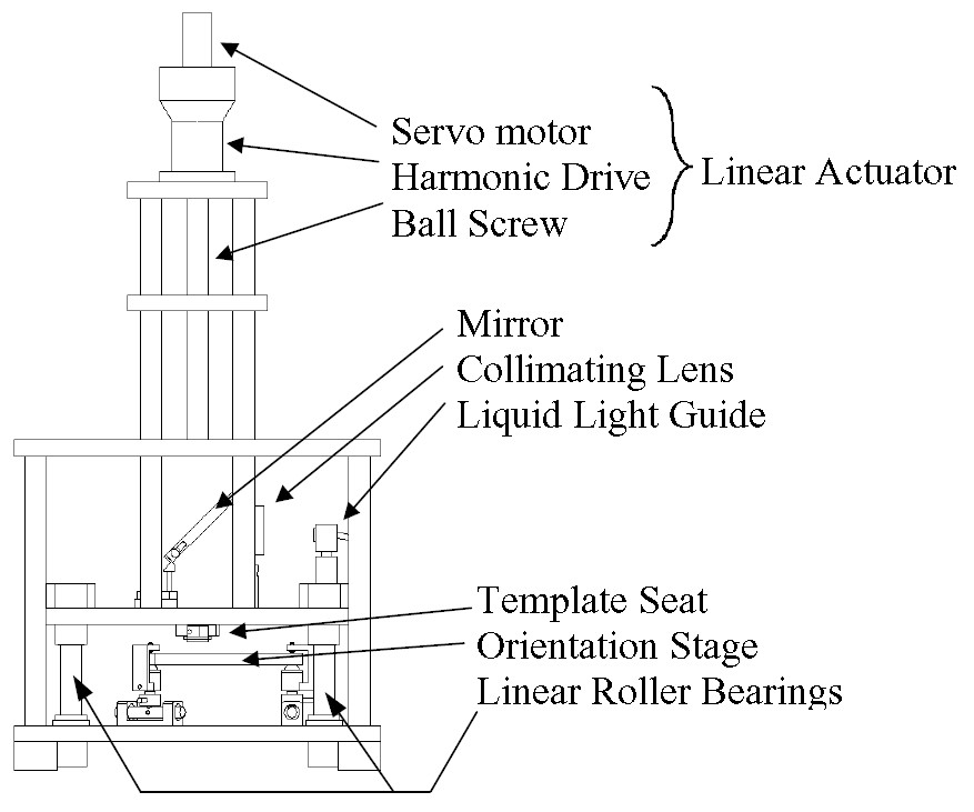
Press This text was adapted from S. Johnson. Designed and built by Steve Johnson and Matthew Colburn, the SFIL Imprint Press was designed to perform many functions. It must hold the wafer and template with minimal distortion and damage ad bring them into parallel contact during imprinting. It must illuminate the wafer with UV light during imprinting, and measure the force required to separate the template and wafer after curing. Figure 1 shows a side view of the SFIL press prototype. To transfer an image, one first mounts a template in the template seat and places a Si wafer on the orientation stage. The template seat and orientation stage lie inside a press constructed of two horizontal plates and four 24 mm diameter linear roller bearings (Agathon, Inc.). The roller bearings are preloaded to only allow vertical motion between the template and the wafer. This vertical motion protects transferred features by minimizing lateral motions between the template and wafer, and hence minimizing shearing forces that would damage the imprinted pattern.
Figure 1. SFIL Imprint Press A linear actuator, consisting of a rotary brushless DC motor (Reliance Electric model #1843622004), a 1:160 gearhead (Harmonic Drive Technologies), and a 0.631 diameter 0.2 pitch precision ground ball screw (Thomson Saginaw) then slowly lowers the template until it rests directly above the Si wafer. The resolution, R, of the actuator in this configuration was calculated to be 0.02 mm/motor count. The use of a preloaded ball screw nut and harmonic drive minimize backlash. Other factors such as compliance of the harmonic drive, motor feedback errors, ball screw machining errors and thermal drift reduce the accuracy of the system to the order of tens of microns. The length of the ball screw allows the template seat to travel almost six inches from its lowest position to its highest position. This allows for easy installation of any future orientation stage designs and lets researchers raise the template to inspect or modify a template or wafer during a printing process. Once the template rests directly above the wafer, a UV-curable etch barrier is dispensed and fills the gap between the template and the wafer via capillary action. After the etch barrier fills the gap between the template and wafer, the linear actuator presses the template onto the wafer. The wafer is mounted on a compliant orientation stage that flexes to allow the orientation of the wafer to match the orientation of the template. A tripod arrangement of three force sensors below the orientation stage senses when the template and wafer make contact. After the template and wafer are pressed together, UV light illuminates the etch barrier. UV light from a Hg vapor lamp (Oriel) is directed through a liquid light guide into a collimating lens and onto a mirror, which directs the light downward through the imprint template and onto the wafer. After the etch barrier is cross-linked, the linear actuator separates teh template and wafer. The template and wafer may then be removed from the machine for inspection and further processing.
| ||||||||||
|
|
||||||||||