
Characterization Techniques |
| We use two methods in our labs at UT to characterize the grafting process. A quartz crystal microbalance (QCM) system is used to probe the growth kinetics and effects of process variables such as film composition, system temperature and pressure of monomer. The solubility characteristics of monomer/polymer pairs are measured using a custom fixed-volume sorption cell. Each of these tools is described in more detail below. Once materials are found that work for this process at UT, they are then imaged at International SEMATECH. |
QCM Chamber |
| The QCM system consists of two QCM sensors housed in a vacuum chamber and enclosed in a convection oven (see figure 1). Using two sensors allows in-situ comparisons of samples; most commonly, this feature is used to compare behavior of exposed and unexposed films. The small sample chamber is preceded by a large ballast chamber which provides constant pressure processing. The ballast chamber is charged from a saturated monomer chamber. The monomer is normally loaded in a glass tube with a glass-to-metal transition to seal it for evacuation of air. Each chamber has a separate line to the vacuum manifold for separate evacuation, and both the monomer and ballast chambers have capacitance manometers to monitor the pressure in situ. Two pneumatic valves connect the monomer and ballast chambers and the ballast and sample chambers, respectively. Three other pneumatic valves provide each chamber with access to vacuum. The system is monitored and controlled via a LabVIEW program. |
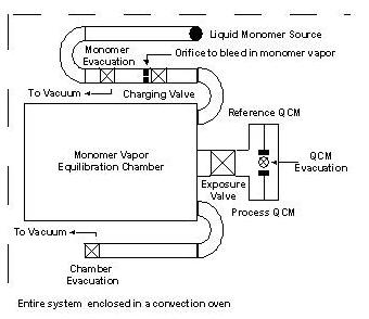 Figure 1. QCM system schematic. |
| In a typical experiment, two gold-coated quartz crystals are coated with a polymer/PAG film of interest. One of these crystals is exposed to ultraviolet radiation at a measured dose; the other is unexposed. The crystals are then loaded in the sample holders and sealed in the sample chamber, which is immediately evacuated. The system equilibrates to a set temperature for at least a half hour, then the ballast chamber is charged to a setpoint pressure (which may take up to a half hour). The crystals are then exposed to a constant pressure of monomer vapor for a set time period (also controlled via LabVIEW software), after which the sample chamber is evacuated. The software monitors the shift in crystal frequency, pressure and temperature at a controllable rate, normally 1 point per second, and saves it to file. Figure 2 displays an example of the data produced by this system. |
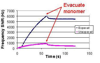 Figure 2. Sample QCM data showing exposed and unexposed samples introduced to monomer vapor for 60 seconds, then evacuated. The exposed sample clearly shows the monomer reaction and graft persistence on the film, while the unexposed sample tracks sorption and desorption of monomer by the film. The small shift immediately after evacuation in the exposed sample is likely desorption of unreacted monomer. |
Sorption Cell |
| The fixed-volume sorption cell consists of three chambers: a monomer or solvent reservoir and a polymer sample chamber connected by a charging chamber (see figure 3). The volumes of the charging chamber and sample chamber are known. The reservoir and sample chamber are each connected to vacuum. The pressures in the reservoir and charging chambers are monitored by two sets of capacitance manometers - each chamber has a 0-100 torr transducer and a 0-1000 torr transducer. The system is enclosed in a convection oven. All parts in contact with the vapor are stainless steel, including the pneumatic valves, ensuring that no background sorption takes place. The system is controlled and monitored via LabVIEW software. |
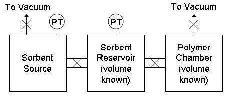 Figure 3. Sorption cell schematic. |
| In a typical experiment, the polymer is loaded in the sample chamber and evacuated. The sample can be either bulk polymer (for equilibrium sorption only) or polymer films coated on silicon wafers and loaded in a special steel holder (for sorption and diffusion). Monomer or solvent (liquid or gas) is loaded in the reservoir, and air removed as appropriate. The charging chamber starts at vacuum. The charging chamber is then loaded with solvent vapor to a set pressure and allowed to equilibrate to temperature for 10 minutes. Then the valve between charging and sample chambers is opened and the system is allowed to equilibrate for several hours or days, depending on the sample. The amount of sorption is calculated from the pressure drop beyond that for volume change. Once equilibrium is reached, the process is repeated without evacuating to obtain an equilibrium sorption isotherm from several runs. If the sample is in film form with known thickness, the diffusion coefficient can be obtained by converting the data to fractional mass uptake and fitting it to the solution to the diffusion equation for diffusion in a plane sheet from a stirred solution of limited volume.1 We have written custom MATLAB software to convert the raw data, find the equilibrium pressure and fit the diffusion equation to find the diffusion coefficient. Because of poor signal to noise ratios on later runs, only the first run (with sample chamber initially at vacuum) is typically used to find the diffusion coefficient. Figure 4 includes a sample isotherm and diffusion fit obtained with this tool. |
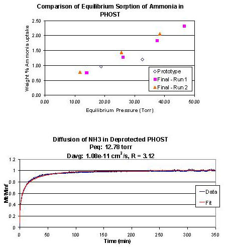 Figure 4. Top - sample sorption data for ammonia in poly(p-hydroxystyrene) (PHOST). Overlay of 3 series of runs showing good agreement. Bottom - diffusion fit for ammonia in PHOST. The Fickian model fits the data well. |